Gambar Teknik Mesin SMK N 3 METRO
Terdapat 6 inti bahasan utama yang harus dikuasai dalam mempelajari Gambar Teknik Mekanik, yaitu :
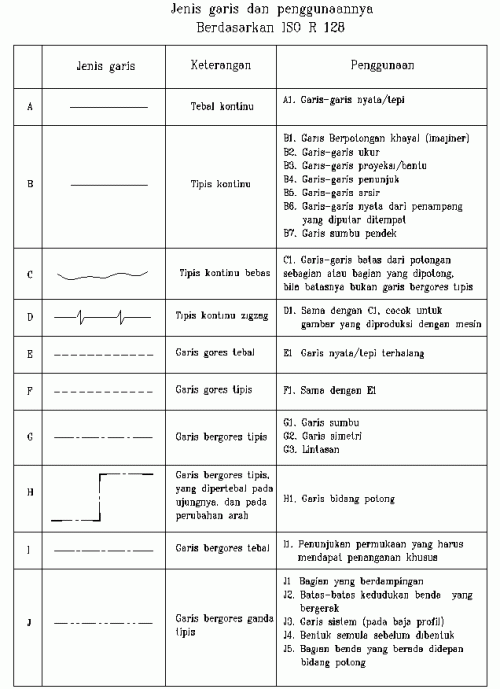
Dalam penggambaran teknik, digunakan beberapa jenis garis yang digunakan sesuai dengan maksud dan
tujuannya. Pada dasarnya, jenis-jenis garis dibagi menjadi 3 bentuk :
1. Garis nyata, yaitu garis kontinu
2. Garis gores, yaitu garis pendek-pendek dengan jarak antara
3. Garis bergores, yaitu garis gores panjang dengan garis gores pendek diantaranya
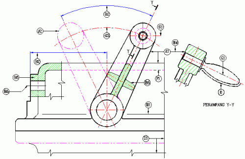
Selain bentuk, harus diperhatikan juga ketebalan garis yang digunakan. Berdasarkan tebalnya, garis dibagi menjadi dua jenis, yaitu garis tebal dan garis tipis, dengan masing-masing kegunaannya. Di bawah ini adalah contoh dari penggunaan variasi garis dan tabel keterangannya
Mengapa kita membutuhkan lebih dari satu pandangan ?
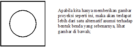
Dalam pembuatan gambar teknik, ada kalanya satu pandangan tidak mencukupi untuk menerjemahkan suatu benda ke dalam gambar proyeksi 2 dimensi. Perhatikan gambar contoh di bawah;
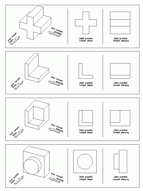
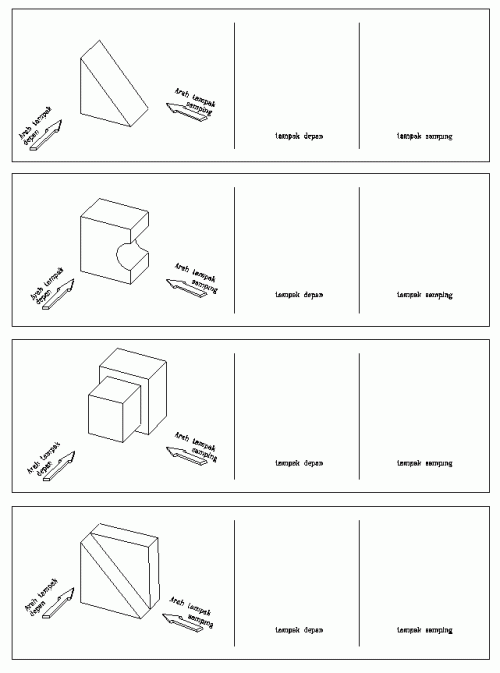
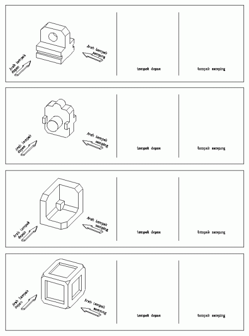
Penguasaan gambar proyeksi diperlukan terutama untuk membuat gambar teknik, bukan untuk membaca gambar teknik, tetapi karena tingkat kesulitan dalam membuat gambar berada di bawah tingkat kesulitan membaca gambar, maka pelajaran proyeksi sebaiknya dilakukan pada tahap awal pengajaran, untuk pendahuluan dalam pelatihan daya bayang dalam pembacaan bentuk gambar 3 dimensi (perspektif).
Sudut pandang proyeksi
Konsep lay out (tata letak) dalam penggambaran gambar teknik terdapat dua macam konsep, yang didasarkan pada sudut pandang gambar, yaitu :
1. Sudut pertama (1st angle) atau proyeksi Eropa

2. Sudut ketiga (3rd angle) atau proyeksi Amerika

Perhatikan gambar di bawah ;

“Kamar-kamar” yang terbentuk dari potongan bidang proyeksi tersebut disebut kwadran, yang
berarti masing-masing kamar dinamakan kwadran pertama, kwandran kedua
sampai keempat, apabila benda diletakkan pada kwadran pertama dan
diproyeksikan pada bidang proyeksi di dalamnya, maka cara seperti ini
disebut cara pandang (cara proyeksi) kwadran pertama (atau sudut
pertama), demikian juga halnya apabila benda diletakkan pada kwadran
ketiga dan diproyeksikan pada bidang-bidang proyeksinya, maka cara
tersebut dinamakan cara pandang sudut ketiga. Secara konsep, proyeksi
sudut kedua dan keempat pun bisa digunakan, tetapi pada prakteknya yang
sekarang ini digunakan hanyalah proyeksi sudut pertama dan ketiga.
Cara proyeksi sudut pertama
Benda seperti yang tampak pada gambar 12a diletakkan di depan bidang-bidang proyeksi seperti pada gambar 12b. Ia diproyeksikan pada bidang belakang menurut garis penglihatan A, dan gambarnya adalah gambar pandangan depan. Tiap garis atau tepi benda tergambar sebagai titik atau garis pada bidang proyeksi. Pada gambar 12b tampak juga proyeksi benda pada bidang bawah menurut arah B, menurut arah C pada bidang proyeksi sebelah kanan , menurut arah D pada bidang proyeksi sebelah kiri, menurut arah E pada bidang proyeksi atas, dan menurut arah F pada bidang depan. Setelah terbentuk semua proyeksi (gambar 12b), bentangkan semua bidang proyeksi menjadi bidang-bidang 2 dimensi (gambar 13a).
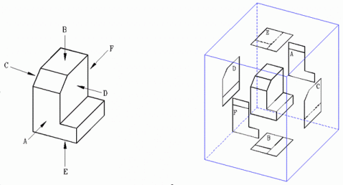 Gambar 12a Gambar12b

Gambar 13a Gambar 13b
Susunan gambar proyeksi harus sedemikian rupa sehingga pandangan depan A sebagai patokan, pandangan atas B terletak dibawah, pandangan kiri C terletak di kanan, pandangan kanan D terletak disebelah kiri, pandangan bawah E terletak diatas, dan pandangan belakang F boleh ditempatkan disebelah kiri atau kanan. Hasil selengkap dapat di lihat pada Gambar 13b.
Dalam gambar, garis-garis tepi yaitu garis-garis batas antara bidang-bidang proyeksi dan garis-garis proyeksi tidak digambar.
Gambar proyeksi demikian disebut gambar proyeksi sudut pertama. Cara ini disebut juga “Cara E” karena cara ini telah banyak dipergunakan dinegara-negara Eropa seperti Jerman, Swiss, Prancis, Rusia dsb.
Cara proyeksi sudut ketiga
Benda yang akan digambar diletak dalam peti dengan sisi-sisi tembus pandang sebagai bidang-bidang proyeksi, seperti pada gambar 14a. Pada tiap-tiap bidang proyeksi akan tampak gambar pandangan dari benda menurut arah penglihatan, yang ditentukan oleh anak panah.
Pandangan depan dalam arah A dipilih sebagai pandangan depan. Pandangan-pandangan lain diproyeksikan pada bidang proyeksi lainnya menuerut gambar 14a, Sisi peti dibuka menjadi satu bidang proyeksi lainnya menurut gabar 14b. Hasil lengkapnya dapat dilihat pada gambar 14c. Dengan pandangan A sebagai patokan, pandangan atas B diletakkan di atas, pandangan kiri C diletakkan di kiri, pandangan kanan D diletakkan di kanan, pandangan bawah E diletakkan di bawah, dan pandangan belakang F dapat diletakkan di kiri atau kanan. Susunan proyeksi demikian disebut gambar proyeksi sudut ketiga, dan disebut juga “Cara A” karena cara ini telah dipakai di Amerika.Negara-negara lain yang banyak mempergunakan cara ini adalah Jepang, Australia, Canada dsb.

Benda kerja Hasil proyeksi

3. PERSPEKTIF
Gambar perspektif adalah gambar 3 dimensi yang merupakan hasil terjemahan dari gambar 2 dimensi, jadi merupakan kebalikan dari gambar proyeksi. Membuat gambar perspektif relatif lebih sulit dibandingkan dengan menggambar proyeksi. Kesulitan pertama adalah menggabungkan seluruh pandangan yang ada sehingga kita bisa membayangkan bentuk benda yang sebenarnya. Kesulitan kedua adalah, walaupun kita sanggup membayangkan bentuk perspektif dari benda tersebut di pikiran kita, seringkali kita kesulitan dalam menggambarkan bentuk tersebut di atas kertas. Menerjemahkan hasil pembacaan kita ke atas kertas memang tidak mutlak harus dilakukan, tetapi akan sangat membantu apabila kita sanggup melakukannya.
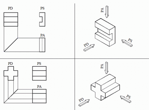
Kemampuan untuk membaca gambar (membayangkan perspektif) lebih banyak diperlukan secara umum daripada kamampuan membuat gambar (membayangkan proyeksi). Kemampuan membuat gambar diperlukan hanya terbatas utuk orang-orang yang tugasnya memang membuat/mencipta gambar teknik, seperti misalnya drafter, designer, atau copies. Tetapi kemampuan membaca gambar diperlukan oleh lebih banyak orang yang tugasnya berkaitan dengan bidang engineering. Oleh karenanya pelatihan gambar perspektif harus dilakukan secara intensif. Teori pada pokok bahasan perspektif ini sangatlah sedikit (untuk tahap dasar), sehingga metoda pelatihan yang terbaik adalah dengan dengan banyak mengerjakan latihan-latihan soal. Di bawah ini adalah beberapa contoh aplikasi gambar perspektif, pelajari dengan baik, kemudian kerjakan latihan soal-soal pada halaman paling belakang
Proyeksi Perspektif
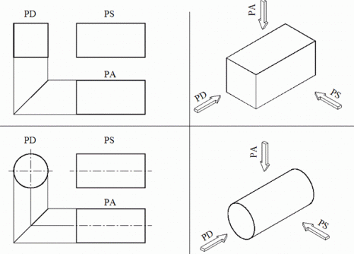
Keterangan : PD (pandangan depan), PS (pandangan samping), PA (pandangan atas)
4. GAMBAR POTONGAN
Tidak jarang ditemui benda-benda dengan rongga–rongga didalamnya. Untuk menggambarkan bagian–bagian ini dipergunakan garis gores, yang menyatakan garis–garis tersembunyi. Jika hal ini dilaksanakan secara taat asas, maka akan dihasilkan sebuah gambar yang rumit sekali dan susah dimengerti. Bayangkan saja jika sebuah lemari roda gigi harus digambar secara lengkap! Untuk mendapatkan gambaran dari bagian–bagian yang tersembunyi ini, bagian yang menutupi dibuang. Gambar demikian disebut gambar potongan, atau disingkat dengan potongan.
Gambar pada gambar 16a memperlihatkan sebuah benda dengan bagian yang tidak kelihatan. Bagian ini dapat dinyatakan dengan garis gores. Jika benda ini dipotong, maka bentuk dalamnya akan lebih jelas lagi. Gambar 16b memperlihatkan cara memotongnya, dan gambar 16c sisa bagian depan setelah bagian yang menutupi disingkirkan. Gambar sisa ini diproyeksikan ke bidang potong, dan hasilnya disebut potongan (gambar 16d. Gambarnya diselesaikan dengan garis tebal.
Dalam hal–hal tertentu bagian–bagian yang terletak di belakang potongan ini, tidak perlu digambar. Hanya jika bagian ini diperlukan, maka bagian di belakang potongan ini digambar dengan garis gores.

Cara–Cara Membuat Potongan
Potongan Dalam Satu Bidang
(1) Potongan Oleh Bidang Potong Melalui Garis Sumbu Dasar
Jika bidang potongan melalui garis sumbu dasar, pada umumnya garis potongnya dan tanda tandanya tidak perlu dijelaskan pada gambar. Foto demikian disebut potongan utama (gambar 17a)
(2) Potongan Yang Tidak Melalui Garis Sumbu Dasar
Jika diperlukan potongan yang tidak melalui sumbu dasar, letak bidang potongnya harus dijelaskan pada garis potongnya (gambar 17b).

Gambar 17a Gambar 17b
Potongan melalui garis sumbu dasar Potongan tidak melalui garis sumbu dasar
Potongan Oleh lebih dari satu bidang
(1) Potongan Meloncat
Untuk menyederhanakan gambar dan penghematan waktu, potongan–potongan dalam beberapa bidang sejajar dapat disatukan. Pada gambar 18a diperlihatkan sebuah benda yang dipotong menurut garis potong A-A. sebenarnya bidang potongannya terdiri atas dua bidang, yang dalam hal ini akan disatukan. Potongan demikian dinamakan potongan meloncat.
(2) Potongan oleh dua bidang berpotongan
Bagian – bagian simetrik dapat digambar pada dua bidang potong yang saling berpotongan. Satu bidang potong merupakan potongan utama, sedangkan bidang yang lain menyudut dengan bidang pertama. Proyeksi pada bidang terakhir ini, setelah diselesaikan menurut aturan-aturan yang berlaku, diputar hingga berhimpit pada bidang proyeksi pertama. Gambar 18b menunjukkan bagaimana caranya membuat gambar potongan demikian.
(3) Potongan pada bidang berdampingan
Potongan pada pipa berbentuk seperti gambar 18c dapat dibuat dengan bidang–bidang yang berdampingan melalui garis sumbunya.
 gambar 18a gambar 18b gambar 18c
Pot. meloncat Pot. dua bidang menyudut Pot. bidang berdampingan
Potongan Separuh
Bagian–bagian simetrik dapat digambar setengahnya sebagai gambar potongan dan setengahnya lagi sebagai pandangan (gambar 19). Dalam gambar ini garis–garis yang tersembunyi tidak perlu digambar dengan garis gores lagi. Karena sudah jelas pada gambar potongan.
Potongan Setempat
Kadang–kadang diperlukan gambaran dari bagian kecil saja dari benda yang tersembunyi, misalnya benda pada gambar 20a. Gambar–gambar 20b dan 20c memperlihatkan gambar yang dipotong setempat dan potongan penuh. Potongan setempat juga dilakukan pada bagian–bagian yang tidak boleh dipotong (gambar 20d).

Bagian-bagian yang tidak boleh dipotong
Ada beberapa jenis benda yang tidak diperboleh kan untuk dipotong, yaitu :
Baut, Paku keling, pasak, poros, sirip penguat, tidak boleh dipotong simbol memanjang.
Arsir
Untuk membedakan gambar potongan dari gambar pandangan, dipergunakan arsir, yaitu garis tipis miring.
Kemiringan garis arsir adalah 45° terhadap garis sumbu, atau terhadap garis gambar. Arsiran dari 2 bagian yang berbeda dan berimpit harus dibedakan pitch-nya.
5. PENUNJUKKAN UKURAN
Poin yang akan dipelajasi pada pokok bahasan ini antara lain :
Ukuran bentuk yaitu ukuran yang menunjukkan panjang dan lebar suatu obyek, termasuk di dalamnya ukuran diameter, radius, dan lain-lain. Sedangkan ukuran posisi adalah ukuran yang menunjukkan jarak obyek tersebut dari suatu bidan referensi tertentu (datum). Contoh ukuran bentuk : Obyek kotak segi empat akan memiliki ukuran bentuk panjang dan lebar, lingkaran akan memiliki ukuran bentuk diameter atau radius, segitiga akan memiliki ukuran bentuk panjang dan tinggi atau panjang dan sudut, dan lain-lain.


Di bawah ini adalah contoh bentuk-bentuk penyederhanaan ukuran yang distandardkan oleh ISO.

6. TOLERANSI
Pada Gambar Teknik, kita mengenal ada beberapa 2 macam toleransi, antara lain
1. Toleransi bentuk dan Posisi
Yang dimaksudkan dengan toleransi bentuk dan posisi adalah, batasan-batasan penyimpangan bentuk atau posisi benda kerja yang diizinkan
2. Toleransi ukuran.
Yang dimaksud dengan toleransi ukuran adalah batasan-batasan penyimpangan ukuran yang diperbolehkan pada suatu benda kerja.
Pada artikel ini kita hanya akan membahas Toleransi ukuran, yang memang banyak kita lihat dan kita pakai sehari-hari. Toleransi ukuran terbagi lagi atas beberapa jenis:
Toleransi Umum
Toleransi umum, adalah besaran angka toleransi yang berlaku untuk semua ukuran yang terdapat pada gambar, kecuali ukuran-ukuran yang telah dicantumi angka toleransi secara khusus. Dengan kata lain, ukuran yang tidak diikuti oleh harga toleransi berarti mengikuti harg atoleransi umum yang berlaku.
Contoh :

Toleransi khusus adalah toleransi di luar angka toleransi umum, dan diletakkan langsung setelah angka nominalnya.

Toleransi Suaian
Biasanya toleransi suaian dipakai pada benda kerja yang berpasangan, seperti misalnya Poros dan As. Untuk toleransi ini biasanya menggunakan symbol Huruf, untuk lubang biasanya menggunakan huruf Kapital / Huruf besar, sedangkan untuk poros menggunakan huruf kecil.
Untuk mudahnya, toleransi suaian ini kita jelaskan dengan mengaplikasikannya pada bentuk lubang dan poros yang berpasangan satu sama lain. Harga toleransi suaian yang dicantumkan menentukan keadaan kelonggaran antara lubang dan poros tersebut. Keadaan suaian dibagi menjadi 3 jenis :
Ukuran yang menggunakan harga toleransi suaian mencantumkan angka nominal, simbol toleransi dan angka toleransinya yang ditulis di dalam kurung (angka ini dituliskan hanya apabila diperlukan, misalnya pihak pengguna gambar tidak memiliki table standar suaian ISO).
Khusus pada gambar susunan, angka nominal dari benda harus mencantumkan harga toleransi untuk kedua benda, lubang maupun poros.

- Jenis-jenis garis
- Proyeksi
- Perspektif
- Potongan
- Penunjukkan ukuran
- Toleransi
1. JENIS-JENIS GARIS
1 Jenis-jenis garis dan pengunaannyaDalam penggambaran teknik, digunakan beberapa jenis garis yang digunakan sesuai dengan maksud dan
tujuannya. Pada dasarnya, jenis-jenis garis dibagi menjadi 3 bentuk :
1. Garis nyata, yaitu garis kontinu
2. Garis gores, yaitu garis pendek-pendek dengan jarak antara
3. Garis bergores, yaitu garis gores panjang dengan garis gores pendek diantaranya
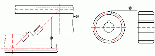
Selain bentuk, harus diperhatikan juga ketebalan garis yang digunakan. Berdasarkan tebalnya, garis dibagi menjadi dua jenis, yaitu garis tebal dan garis tipis, dengan masing-masing kegunaannya. Di bawah ini adalah contoh dari penggunaan variasi garis dan tabel keterangannya

Gambar 1
Contoh penggunaan variasi jenis garis
Contoh penggunaan variasi jenis garis
Tabel jenis-jenis garis dan penggunaannya
Contoh lain penggunaan garis
2. PROYEKSI
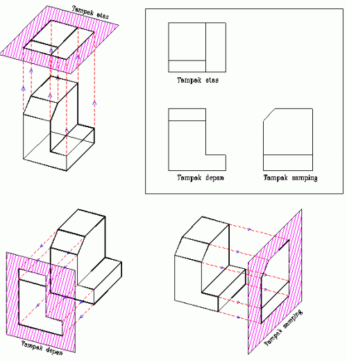
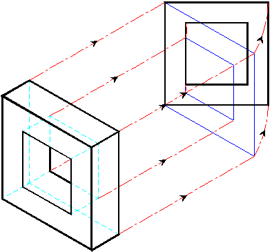
Proyeksi 2 dimensi adalah penerjemahan suatu benda bentuk 3 dimensi kedalam bentuk 2 dimensi, artinya benda tersebut digambarkan hanya dari salah satu sudut pandang, dan oleh sebab itu gambar proyeksi 2 dimensi hanya memiliki dua komponen ukuran , yaitu panjang dan lebar. Kekurangan satu elemen ukuran yang lain yaitu ukuran tinggi dikompensasi dengan di buatkan proyeksi dari sudut pandang yang lain yang dapat memperlihatkan ketinggian benda tersebut. Apabila benda yang hendak diproyeksikan memiliki kerumitan yang tinggi, tidak menutup kemungkinan gambar proyeksi yang dibuat menampilkan banyak sudut pandang. Gambar tampilan proyeksi 2 dimensi diusahakan menampilkan sesedikit mungkin pandangan dengan memperhatikan faktor kerapian dan kemudahan pembacaan gambar.
Konsep proyeksi
Konsep proyeksi
Dalam pembuatan gambar teknik, ada kalanya satu pandangan tidak mencukupi untuk menerjemahkan suatu benda ke dalam gambar proyeksi 2 dimensi. Perhatikan gambar contoh di bawah;

Gambar 6. Pandangan depan suatu benda
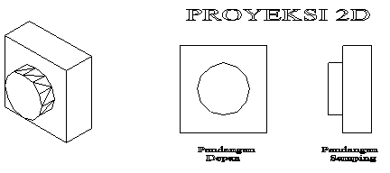
Gambar 7. Alternatif bentuk
Pada gambar 6 terlihat bahwa semua bentuk benda tersebut memiliki
gambar proyeksi yang sama seperti gambar 3 (dilihat dari pandangan
depan). Untuk mengetahui dengan pasti bagaimana bentuk benda yang
sebenarnya, kita harus menambah gambar proyeksi tersebut dengan
mengambil sudut pandang yang lain, bisa 2 pandangan, 3 pandangan atau
lebih, tergantung dari tingkat kerumitan yang dimiliki oleh benda
tersebut. Peraturan dalam menentukan jumlah sudut pandang proyeksi
adalah buatlah pandangan sesedikit mungkin, dengan menampilkan seluruh
informasi yang diperlukan, dengan catatan keseluruhan gambar tersebut
mudah dibaca semua orang (artinya lebih baik membuat gambar 3 pandangan
dengan kondisi yang mudah dibaca daripada membuat gambar 2 pandangan
dengan kondisi yang sulit dibaca).
Gambar proyeksi
Dari gambar di atas terlihat bahwa untuk
menerjemahkan benda 3d (gambar 7) diperlukan paling sedikit 2 pandangan,
bisa terdiri dari bermacam kombinasi pandangan, bisa tediri dari
pandangan depan + pandangan samping, atau pandangan depan + pandangan
atas, atau yang lainnya sepanjang semua informasi bentuk tercakup dalam
gambar proyeksi tersebut.
Berikut ini adalah contoh-contoh proyeksi dari benda-benda sederhana, dilanjutkan dengan soal-soal latihannya :


Penguasaan gambar proyeksi diperlukan terutama untuk membuat gambar teknik, bukan untuk membaca gambar teknik, tetapi karena tingkat kesulitan dalam membuat gambar berada di bawah tingkat kesulitan membaca gambar, maka pelajaran proyeksi sebaiknya dilakukan pada tahap awal pengajaran, untuk pendahuluan dalam pelatihan daya bayang dalam pembacaan bentuk gambar 3 dimensi (perspektif).
Sudut pandang proyeksi
Konsep lay out (tata letak) dalam penggambaran gambar teknik terdapat dua macam konsep, yang didasarkan pada sudut pandang gambar, yaitu :
1. Sudut pertama (1st angle) atau proyeksi Eropa

2. Sudut ketiga (3rd angle) atau proyeksi Amerika

Perhatikan gambar di bawah ;

Cara proyeksi berdasarkan kwadran
Cara proyeksi sudut pertama
Benda seperti yang tampak pada gambar 12a diletakkan di depan bidang-bidang proyeksi seperti pada gambar 12b. Ia diproyeksikan pada bidang belakang menurut garis penglihatan A, dan gambarnya adalah gambar pandangan depan. Tiap garis atau tepi benda tergambar sebagai titik atau garis pada bidang proyeksi. Pada gambar 12b tampak juga proyeksi benda pada bidang bawah menurut arah B, menurut arah C pada bidang proyeksi sebelah kanan , menurut arah D pada bidang proyeksi sebelah kiri, menurut arah E pada bidang proyeksi atas, dan menurut arah F pada bidang depan. Setelah terbentuk semua proyeksi (gambar 12b), bentangkan semua bidang proyeksi menjadi bidang-bidang 2 dimensi (gambar 13a).
 Gambar 12a Gambar12b
Gambar 13a Gambar 13b
Susunan gambar proyeksi harus sedemikian rupa sehingga pandangan depan A sebagai patokan, pandangan atas B terletak dibawah, pandangan kiri C terletak di kanan, pandangan kanan D terletak disebelah kiri, pandangan bawah E terletak diatas, dan pandangan belakang F boleh ditempatkan disebelah kiri atau kanan. Hasil selengkap dapat di lihat pada Gambar 13b.
Dalam gambar, garis-garis tepi yaitu garis-garis batas antara bidang-bidang proyeksi dan garis-garis proyeksi tidak digambar.
Gambar proyeksi demikian disebut gambar proyeksi sudut pertama. Cara ini disebut juga “Cara E” karena cara ini telah banyak dipergunakan dinegara-negara Eropa seperti Jerman, Swiss, Prancis, Rusia dsb.
Cara proyeksi sudut ketiga
Benda yang akan digambar diletak dalam peti dengan sisi-sisi tembus pandang sebagai bidang-bidang proyeksi, seperti pada gambar 14a. Pada tiap-tiap bidang proyeksi akan tampak gambar pandangan dari benda menurut arah penglihatan, yang ditentukan oleh anak panah.
Pandangan depan dalam arah A dipilih sebagai pandangan depan. Pandangan-pandangan lain diproyeksikan pada bidang proyeksi lainnya menuerut gambar 14a, Sisi peti dibuka menjadi satu bidang proyeksi lainnya menurut gabar 14b. Hasil lengkapnya dapat dilihat pada gambar 14c. Dengan pandangan A sebagai patokan, pandangan atas B diletakkan di atas, pandangan kiri C diletakkan di kiri, pandangan kanan D diletakkan di kanan, pandangan bawah E diletakkan di bawah, dan pandangan belakang F dapat diletakkan di kiri atau kanan. Susunan proyeksi demikian disebut gambar proyeksi sudut ketiga, dan disebut juga “Cara A” karena cara ini telah dipakai di Amerika.Negara-negara lain yang banyak mempergunakan cara ini adalah Jepang, Australia, Canada dsb.

Benda kerja Hasil proyeksi

Susunan gambar hasil proyeksi
Gambar perspektif adalah gambar 3 dimensi yang merupakan hasil terjemahan dari gambar 2 dimensi, jadi merupakan kebalikan dari gambar proyeksi. Membuat gambar perspektif relatif lebih sulit dibandingkan dengan menggambar proyeksi. Kesulitan pertama adalah menggabungkan seluruh pandangan yang ada sehingga kita bisa membayangkan bentuk benda yang sebenarnya. Kesulitan kedua adalah, walaupun kita sanggup membayangkan bentuk perspektif dari benda tersebut di pikiran kita, seringkali kita kesulitan dalam menggambarkan bentuk tersebut di atas kertas. Menerjemahkan hasil pembacaan kita ke atas kertas memang tidak mutlak harus dilakukan, tetapi akan sangat membantu apabila kita sanggup melakukannya.
Kemampuan untuk membaca gambar (membayangkan perspektif) lebih banyak diperlukan secara umum daripada kamampuan membuat gambar (membayangkan proyeksi). Kemampuan membuat gambar diperlukan hanya terbatas utuk orang-orang yang tugasnya memang membuat/mencipta gambar teknik, seperti misalnya drafter, designer, atau copies. Tetapi kemampuan membaca gambar diperlukan oleh lebih banyak orang yang tugasnya berkaitan dengan bidang engineering. Oleh karenanya pelatihan gambar perspektif harus dilakukan secara intensif. Teori pada pokok bahasan perspektif ini sangatlah sedikit (untuk tahap dasar), sehingga metoda pelatihan yang terbaik adalah dengan dengan banyak mengerjakan latihan-latihan soal. Di bawah ini adalah beberapa contoh aplikasi gambar perspektif, pelajari dengan baik, kemudian kerjakan latihan soal-soal pada halaman paling belakang
Proyeksi Perspektif

Keterangan : PD (pandangan depan), PS (pandangan samping), PA (pandangan atas)

Contoh gambar perspektif
Tidak jarang ditemui benda-benda dengan rongga–rongga didalamnya. Untuk menggambarkan bagian–bagian ini dipergunakan garis gores, yang menyatakan garis–garis tersembunyi. Jika hal ini dilaksanakan secara taat asas, maka akan dihasilkan sebuah gambar yang rumit sekali dan susah dimengerti. Bayangkan saja jika sebuah lemari roda gigi harus digambar secara lengkap! Untuk mendapatkan gambaran dari bagian–bagian yang tersembunyi ini, bagian yang menutupi dibuang. Gambar demikian disebut gambar potongan, atau disingkat dengan potongan.
Gambar pada gambar 16a memperlihatkan sebuah benda dengan bagian yang tidak kelihatan. Bagian ini dapat dinyatakan dengan garis gores. Jika benda ini dipotong, maka bentuk dalamnya akan lebih jelas lagi. Gambar 16b memperlihatkan cara memotongnya, dan gambar 16c sisa bagian depan setelah bagian yang menutupi disingkirkan. Gambar sisa ini diproyeksikan ke bidang potong, dan hasilnya disebut potongan (gambar 16d. Gambarnya diselesaikan dengan garis tebal.
Dalam hal–hal tertentu bagian–bagian yang terletak di belakang potongan ini, tidak perlu digambar. Hanya jika bagian ini diperlukan, maka bagian di belakang potongan ini digambar dengan garis gores.

Gambar 16. Penjelasan Mengenai Potongan
Potongan Dalam Satu Bidang
(1) Potongan Oleh Bidang Potong Melalui Garis Sumbu Dasar
Jika bidang potongan melalui garis sumbu dasar, pada umumnya garis potongnya dan tanda tandanya tidak perlu dijelaskan pada gambar. Foto demikian disebut potongan utama (gambar 17a)
(2) Potongan Yang Tidak Melalui Garis Sumbu Dasar
Jika diperlukan potongan yang tidak melalui sumbu dasar, letak bidang potongnya harus dijelaskan pada garis potongnya (gambar 17b).

Gambar 17a Gambar 17b
Potongan melalui garis sumbu dasar Potongan tidak melalui garis sumbu dasar
Potongan Oleh lebih dari satu bidang
(1) Potongan Meloncat
Untuk menyederhanakan gambar dan penghematan waktu, potongan–potongan dalam beberapa bidang sejajar dapat disatukan. Pada gambar 18a diperlihatkan sebuah benda yang dipotong menurut garis potong A-A. sebenarnya bidang potongannya terdiri atas dua bidang, yang dalam hal ini akan disatukan. Potongan demikian dinamakan potongan meloncat.
(2) Potongan oleh dua bidang berpotongan
Bagian – bagian simetrik dapat digambar pada dua bidang potong yang saling berpotongan. Satu bidang potong merupakan potongan utama, sedangkan bidang yang lain menyudut dengan bidang pertama. Proyeksi pada bidang terakhir ini, setelah diselesaikan menurut aturan-aturan yang berlaku, diputar hingga berhimpit pada bidang proyeksi pertama. Gambar 18b menunjukkan bagaimana caranya membuat gambar potongan demikian.
(3) Potongan pada bidang berdampingan
Potongan pada pipa berbentuk seperti gambar 18c dapat dibuat dengan bidang–bidang yang berdampingan melalui garis sumbunya.
 gambar 18a gambar 18b gambar 18c
Pot. meloncat Pot. dua bidang menyudut Pot. bidang berdampingan
Potongan Separuh
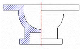
Bagian–bagian simetrik dapat digambar setengahnya sebagai gambar potongan dan setengahnya lagi sebagai pandangan (gambar 19). Dalam gambar ini garis–garis yang tersembunyi tidak perlu digambar dengan garis gores lagi. Karena sudah jelas pada gambar potongan.
Gambar 19. Potongan separuh
Kadang–kadang diperlukan gambaran dari bagian kecil saja dari benda yang tersembunyi, misalnya benda pada gambar 20a. Gambar–gambar 20b dan 20c memperlihatkan gambar yang dipotong setempat dan potongan penuh. Potongan setempat juga dilakukan pada bagian–bagian yang tidak boleh dipotong (gambar 20d).

gambar 20a gambar 20b
gambar 20c. Potongan penuh gambar 20d
Ada beberapa jenis benda yang tidak diperboleh kan untuk dipotong, yaitu :
Baut, Paku keling, pasak, poros, sirip penguat, tidak boleh dipotong simbol memanjang.
Arsir
Untuk membedakan gambar potongan dari gambar pandangan, dipergunakan arsir, yaitu garis tipis miring.
Kemiringan garis arsir adalah 45° terhadap garis sumbu, atau terhadap garis gambar. Arsiran dari 2 bagian yang berbeda dan berimpit harus dibedakan pitch-nya.
5. PENUNJUKKAN UKURAN
Poin yang akan dipelajasi pada pokok bahasan ini antara lain :
- Jenis ukuran (berdasarkan obyek yang di beri ukuran)
- Datum
- Peraturan-peraturan dalam memberikan ukuran
Ukuran bentuk yaitu ukuran yang menunjukkan panjang dan lebar suatu obyek, termasuk di dalamnya ukuran diameter, radius, dan lain-lain. Sedangkan ukuran posisi adalah ukuran yang menunjukkan jarak obyek tersebut dari suatu bidan referensi tertentu (datum). Contoh ukuran bentuk : Obyek kotak segi empat akan memiliki ukuran bentuk panjang dan lebar, lingkaran akan memiliki ukuran bentuk diameter atau radius, segitiga akan memiliki ukuran bentuk panjang dan tinggi atau panjang dan sudut, dan lain-lain.
Untuk memberikan ukuran posisi kita harus menentukan posisi datum terlebih dahulu. Datum adalah bidang referensi. Datum ini bisa berupa titik sudut, garis, ataupun bidang pada suatu benda. Penentuan datum ini didasarkan oleh hal-hal berikut ini :
- Fungsi dari benda
- Kemudahan pengerjaan
- Kemudahan perakitan

Gambar 22. Contoh Datum
Aturan-aturan dalam pemberian ukuran :- Ukuran harus cukup jelas untuk bisa dibaca dengan mudah
- Hindari pemberian ukuran ganda
- Usahakan untuk menempatkan ukuran diluar area benda
- Pastikan angka ukuran dan garis panahnya tidak ditabrak oleh garis yang lain

Gambar 23. Contoh cara penunjukkan ukuran yang benar
Hal penting yang lain dalam penunjukkan ukuran adalah penyederhanaan
ukuran, artinya penunjukkan ukuran dibuat sedemikian rupa hingga tidak
memakan banyak area gambar yang berarti membuat gambar menjadi lebih
lapang dan mudah dibaca. Selain itu dengan efisiensi ukuran, gambar
benda yang ditampilkan bisa lebih besar (skala), dan pembacaan akan
lebih mudah. Penyederhanaan boleh dilakukan dengan tanpa mengurangi
fungsi dari ukuran itu sendiri.Di bawah ini adalah contoh bentuk-bentuk penyederhanaan ukuran yang distandardkan oleh ISO.

Gambar 24. Contoh gambar penyederhanaan ukuran
Pada Gambar Teknik, kita mengenal ada beberapa 2 macam toleransi, antara lain
1. Toleransi bentuk dan Posisi
Yang dimaksudkan dengan toleransi bentuk dan posisi adalah, batasan-batasan penyimpangan bentuk atau posisi benda kerja yang diizinkan
2. Toleransi ukuran.
Yang dimaksud dengan toleransi ukuran adalah batasan-batasan penyimpangan ukuran yang diperbolehkan pada suatu benda kerja.
Pada artikel ini kita hanya akan membahas Toleransi ukuran, yang memang banyak kita lihat dan kita pakai sehari-hari. Toleransi ukuran terbagi lagi atas beberapa jenis:
- Toleransi Umum
- Toleransi Khusus
- Toleransi Suaian
Toleransi Umum
Toleransi umum, adalah besaran angka toleransi yang berlaku untuk semua ukuran yang terdapat pada gambar, kecuali ukuran-ukuran yang telah dicantumi angka toleransi secara khusus. Dengan kata lain, ukuran yang tidak diikuti oleh harga toleransi berarti mengikuti harg atoleransi umum yang berlaku.
Contoh :

Gambar 25. Contoh toleransi umum
Toleransi KhususToleransi khusus adalah toleransi di luar angka toleransi umum, dan diletakkan langsung setelah angka nominalnya.

Gambar 26. Contoh toleransi khusus
Toleransi Suaian
Biasanya toleransi suaian dipakai pada benda kerja yang berpasangan, seperti misalnya Poros dan As. Untuk toleransi ini biasanya menggunakan symbol Huruf, untuk lubang biasanya menggunakan huruf Kapital / Huruf besar, sedangkan untuk poros menggunakan huruf kecil.
Untuk mudahnya, toleransi suaian ini kita jelaskan dengan mengaplikasikannya pada bentuk lubang dan poros yang berpasangan satu sama lain. Harga toleransi suaian yang dicantumkan menentukan keadaan kelonggaran antara lubang dan poros tersebut. Keadaan suaian dibagi menjadi 3 jenis :
- Suaian longgar (clearance fit)
- Suaian luncur (sliding fit)
- Suaian sesak (interference fit)
Ukuran yang menggunakan harga toleransi suaian mencantumkan angka nominal, simbol toleransi dan angka toleransinya yang ditulis di dalam kurung (angka ini dituliskan hanya apabila diperlukan, misalnya pihak pengguna gambar tidak memiliki table standar suaian ISO).
Khusus pada gambar susunan, angka nominal dari benda harus mencantumkan harga toleransi untuk kedua benda, lubang maupun poros.

Gambar 27. Contoh penulisan angka toleransi
